Pneumatic Artificial Muscle Actuator
Neurorehabilitation and Robotics Laboratory @ CUHK
Project Overview
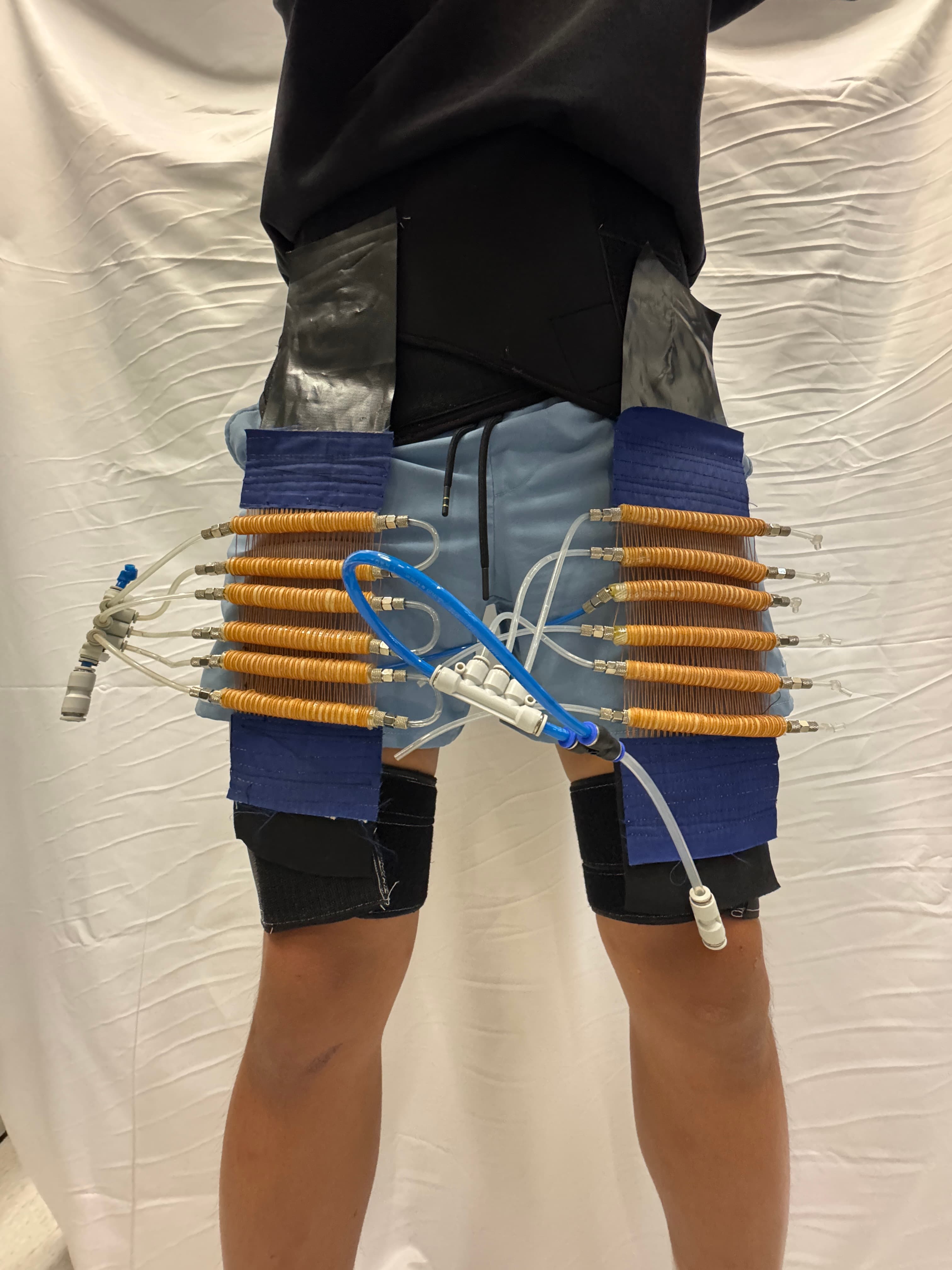
As a Researcher at the Chinese University of Hong Kong's Neurorehabilitation and Robotics Laboratory, I am designing and fabricating a McKibben pneumatic artificial muscle actuator for quadriceps assistance, targeting soft robotic rehabilitation applications for chronic stroke patients. The actuator is currently rated at 29.5 N of pulling force at 500 kPa per muscle.
Key Contributions
- •Design and fabrication of a McKibben pneumatic artificial muscle actuator
- •Engineering of actuator geometry and materials for quadriceps assistance
- •CAD modeling and rapid prototyping of actuator components via 3D printing
- •Development targeted at soft robotic rehabilitation applications for chronic stroke patients
Research Impact
This work contributes to the development of soft, compliant actuators that can safely assist movement in rehabilitation settings. By advancing pneumatic artificial muscle technology for quadriceps support, this research aims to improve mobility and recovery outcomes for chronic stroke patients.
This research is ongoing.
Hydraulic Artificial Muscle Exosuit
Quadriceps and hip flexor assistance for post-stroke gait
1. Research Goal
Stroke damages the descending motor pathways, so survivors lose voluntary force on the affected side. Knee extensor and hip flexor weakness are among the strongest predictors of reduced walking speed. Three specific gait failures follow.
- •Knee buckling at loading response, because the extensors fail to resist the flexion moment when body weight lands.
- •Reduced limb advancement in swing, because the hip flexors and rectus femoris fail to accelerate the thigh forward.
- •Inability to climb stairs, because stair ascent demands near maximal knee extensor torque on one limb.
Patients compensate with circumduction, hip hiking and knee hyperextension. These patterns raise metabolic cost and fall risk.
Goal: build a soft wearable exosuit that adds knee extensor and hip flexor torque on the affected limb during walking and stair ascent, using hydraulic artificial muscles driven by a single reversing pump, triggered by inertial sensing of gait intent.
Priority order: level walking swing assistance, then loading response support, then stair ascent, then sit to stand. Scope is one limb, tethered bench operation, IMU based intent detection. Bilateral assistance, battery operation and clinical trials are out of scope.
| ID | Functional requirement | Target |
|---|---|---|
| FR-1 | Peak assistive force at the distal anchor | 150 N |
| FR-2 | Contraction ratio at operating pressure | ≥ 20% |
| FR-3 | Operating pressure | 1.0 MPa |
| FR-4 | Actuation latency, trigger to 90% force | < 150 ms |
| FR-5 | Gait event detection accuracy | ≥ 95% of steps |
| FR-6 | Worn mass excluding power unit | < 2.0 kg |
| FR-7 | Skin pressure under any interface | < 20 kPa sustained |
| FR-8 | Burst margin on the muscle assembly | 3× operating pressure |
Table 1. Functional requirements.
2. Background
The rectus femoris crosses two joints. It flexes the hip and extends the knee. A single artificial muscle running from a pelvic anchor to a shank anchor reproduces that line of action, so one actuator serves both target functions and worn mass stays low. The moment arm at each joint changes through the gait cycle, so timing matters more than magnitude.
The soft exosuit field is dominated by cable driven designs from the Harvard Biodesign Lab, which demonstrated improved paretic propulsion after stroke and established human in the loop optimization of assistance profiles. Artificial muscle exosuits are rarer and almost always pneumatic. Hydraulic McKibben actuators are common in high force robotics but rare in wearables, mainly because of fluid mass and leak risk. That gap is what this project addresses.
| Ref | Citation | Relevance |
|---|---|---|
| R1 | Chou and Hannaford, IEEE T-RA 12(1), 90-102, 1996 | Force model used for all muscle sizing here |
| R2 | Tondu, J. Intell. Mater. Syst. Struct. 23(3), 225-253, 2012 | McKibben modelling review, including friction losses |
| R3 | Tiwari et al., J. Intell. Mater. Syst. Struct. 23(3), 301-312, 2012 | Hydraulic artificial muscles, force density versus pneumatic |
| R4 | Asbeck et al., Int. J. Robotics Research 34(6), 744-762, 2015 | Soft exosuit architecture and textile load paths |
| R5 | Awad et al., Science Translational Medicine 9(400), 2017 | Soft exosuit improves walking after stroke |
| R6 | Yandell et al., J. NeuroEng. Rehabil. 14:40, 2017 | Interface dynamics; why anchors dominate performance |
| R7 | Ding et al., Science Robotics 3(15), 2018 | Human in the loop optimization of hip assistance |
| R8 | Zhang et al., 2022 [full citation required] | Adaptive oscillators with LSBoost for gait phase estimation |
| R9 | Kim et al., 2022 [full citation required] | HIL optimization with CMA-ES; hip flexion joint efficiency |
Table 2. Core reading list. Verify every citation and add DOIs before release.
3. System Overview
A fixed camera views the affected limb in the sagittal plane. Software extracts thigh angle from hip and knee landmarks, detects the onset of knee lift from thigh angular velocity, then commands the motor controller over RS485 Modbus. A thigh IMU streams angular rate on the same clock as an independent check and as the deployment sensor. The motor drives the pump, which pressurizes the muscle bladder. The braided sleeve converts radial expansion into axial contraction, pulling the shank anchor toward the pelvic anchor. At the end of swing the pump reverses and the muscle relaxes.
One pump drives two muscles reciprocally. Forward rotation pressurizes one while the other relaxes. This matches the reciprocal nature of gait and halves the pump count. The cost is that co-contraction is impossible by construction. Accept it or change the architecture; there is no control workaround.
4. Actuator Design Analysis
A weighted decision matrix records why the project uses hydraulic artificial muscles. Rerun the scoring with different weights before accepting the result.
| ID | Technology | Principle | Decisive limitation |
|---|---|---|---|
| A | Pneumatic McKibben | Compressed air inflates a bladder inside a braided sleeve | Gas compliance causes lag; portable compressor is heavy and loud |
| B | Hydraulic McKibben | Same geometry, incompressible working fluid | No inherent compliance; leaks land on the patient; not as instantaneous as pneumatics |
| C | Bowden cable | Off board motor spools cable in a flexible sheath | Tension concentrates at the anchor; sheath friction and wear |
| D | Rigid geared joint | Motor and gearbox on a frame spanning the joint | Heavy and distal; joint misalignment causes skin shear |
| E | Shape memory alloy | Joule heated NiTi wire contracts on phase change | Cooling governs the return stroke, seconds not milliseconds |
| F | Twisted coiled polymer | Twist inserted nylon fibre contracts on heating | Same thermal bandwidth failure as SMA |
| G | Dielectric elastomer | Electrostatic pressure deforms a compliant film | Kilovolt supply beside a patient; fabrication unsolved |
Table 3. Candidate technologies.
| Code | Criterion | Weight | Basis |
|---|---|---|---|
| C1 | Force to worn mass ratio | 20% | FR-1, FR-6. Distal mass raises metabolic cost directly |
| C2 | Bandwidth and response latency | 15% | FR-4. Gait events demand sub 150 ms response |
| C3 | Interface safety and compliance | 15% | FR-7. Device sits on impaired, often insensate tissue |
| C4 | Untethered power practicality | 15% | Determines whether the device leaves the lab |
| C5 | Transmission stiffness and control fidelity | 10% | Force must track command, not the compliance of the medium |
| C6 | Manufacturability with lab resources | 10% | Injection molding, braiding rig and 3D printers on site |
| C7 | Durability and maintenance | 10% | Thousands of cycles per session |
| C8 | Cost and lead time | 5% | Constrained but not decisive at prototype stage |
Table 4. Criteria and weights. Scoring is 1 (fails a requirement) to 5 (no practical limitation).
| Technology | C1 (20) | C2 (15) | C3 (15) | C4 (15) | C5 (10) | C6 (10) | C7 (10) | C8 (5) | Score | Rank |
|---|---|---|---|---|---|---|---|---|---|---|
| A Pneumatic McKibben | 4 | 3 | 5 | 2 | 2 | 4 | 4 | 4 | 3.50 | 3 |
| B Hydraulic McKibben | 5 | 4 | 4 | 4 | 5 | 4 | 3 | 4 | 4.20 | 1 |
| C Bowden cable | 4 | 5 | 3 | 4 | 4 | 3 | 3 | 3 | 3.75 | 2 |
| D Rigid geared joint | 2 | 5 | 2 | 3 | 5 | 2 | 4 | 2 | 3.10 | 4 |
| E Shape memory alloy | 5 | 1 | 3 | 2 | 3 | 3 | 2 | 4 | 2.90 | 5 |
| F Twisted coiled polymer | 4 | 1 | 4 | 2 | 2 | 4 | 2 | 5 | 2.90 | 5 |
| G Dielectric elastomer | 2 | 4 | 3 | 1 | 2 | 1 | 1 | 2 | 2.10 | 7 |
Table 5. Weighted decision matrix. Headers show the criterion code above its weight.
Hydraulic wins on force density, control fidelity and power unit size. It loses a point on interface safety, because an incompressible system has no inherent give, and a point on durability, because leaks are the dominant failure mode. Bowden cable ranks second and is the credible fallback if the hydraulic route stalls. Thermal actuators fail the latency requirement outright and dielectric elastomers fail safety review before performance testing.
Reasoning behind the scores that decide the outcome:
- •Hydraulic C1 = 5 and C5 = 5. Incompressible fluid sustains far higher pressure in the same braid, so a slimmer muscle meets the force target, and pump displacement maps almost directly to contraction, which makes open loop control viable.
- •Hydraulic C3 = 4 and C7 = 3. These are the honest weaknesses. There is no gas cushion, so a mechanical relief valve and a mechanical force limit are mandatory. Leaks are messy and land on the patient.
- •Pneumatic C3 = 5 but C4 = 2 and C5 = 2. Gas compliance is a genuine safety feature, and the same compliance destroys force control precision and forces a heavy, loud compressor.
- •Bowden C2 = 5 but C3 = 3. Fastest response of any option, held back by tension concentrating at the anchor and sheath friction introducing hysteresis.
- •SMA and twisted polymer both score C2 = 1. Cooling governs the return stroke and takes seconds. This fails FR-4 by an order of magnitude, so nothing else about them matters.
4.1 Pneumatic versus hydraulic
These two share geometry, manufacturing process and force model. Only the fluid differs, which makes the comparison sharp.
| Property | Pneumatic (air) | Hydraulic (liquid) | Consequence |
|---|---|---|---|
| Compressibility | High | Negligible, bulk modulus of water ≈ 2.2 GPa | Hydraulic force tracks the pump command without a compliance lag |
| Operating pressure | 0.2 to 0.6 MPa | 1 MPa and above | Same braid diameter delivers several times the force |
| Inherent compliance | Yes, from the gas | None | Hydraulic needs an engineered relief path, not an optional extra |
| Stored energy in fluid | Large | Almost none | Hydraulic failure releases far less energy |
| Supply hardware | Compressor, accumulator, regulator | Pump, reservoir, relief valve | Hydraulic unit is smaller and quieter at equal output |
| Leak consequence | Cosmetic | Wets patient and equipment | Sealing discipline at every fitting |
| Added fluid mass | Negligible | Real, in lines and reservoir | Keep line lengths short and bore small |
Table 6. Working fluid comparison. Record which fluid is actually used, since it sets seal material and leak consequences.
4.2 Decision and sensitivity
- 1.Force density. Incompressible fluid supports higher pressure in the same braid, so the muscle meets the force target at a diameter that fits under clothing.
- 2.Control fidelity. Pump displacement maps to contraction, with no compliance between command and force. This is what makes reactive IMU triggering feasible at all.
- 3.Power unit size. A small pump and reservoir beat a portable compressor on mass, volume and noise.
The result holds for weight changes of about 5 percentage points. It does not survive a doubling of the weight on portability, where Bowden cable overtakes, or on durability, where hydraulic falls behind both alternatives.
5. Artificial Muscle Manufacturing
The muscle has three parts: an injection molded elastomeric bladder, a braided sleeve wrapped around it by machine, and two end fittings that seal and anchor both ends. Fluid pumped into the bladder inflates it radially. The braid constrains that expansion, its helical fibers rotate toward the circumferential direction, and because fiber length is fixed the sleeve shortens along its axis. The muscle only pulls. It never pushes.
5.1 Force model
D₀ is resting braid diameter, P gauge pressure, ε contraction ratio, θ₀ resting braid angle from the muscle axis. At zero contraction this reduces to the blocked force πPr₀²(3cos²θ₀ − 1)/sin²θ₀.
- •Force falls as the muscle contracts, reaching zero at θ = 54.7 degrees. Size the muscle so the working range sits where force is still useful.
- •Force scales linearly with pressure and with the square of diameter. Diameter is limited by what fits under clothing, so pressure is the available lever.
The model is ideal. Real hydraulic McKibben muscles produce roughly 15 to 25 percent less, because of bladder wall elasticity, braid friction and end effects. Always validate against a load cell, and never quote modelled force as measured force. For burst risk, back calculate pressure from measured force and braid angle rather than reading force alone.
5.2 Bladder: injection molding
Molding rather than extrusion or dipping gives repeatable wall thickness and integrated end geometry, which is what makes the assembly seal at high pressure. Sequence: dry the material, load the barrel, inject into the closed tool over a core pin, hold under packing pressure, cool in tool, eject and strip from the pin, trim and inspect.
- •Wall thickness sets both burst pressure and parasitic stiffness. Thicker walls survive more pressure but absorb input energy and reduce net contraction.
- •Thickness must be uniform. A thin spot becomes the burst point.
- •The bladder must be longer than the braid at rest so it never carries axial tension. The braid carries the load, the bladder only seals.
5.3 Braid: winding machine
A dedicated machine wraps fiber around the molded bladder. Hand braiding does not hold a consistent braid angle, and braid angle is the most influential geometric parameter in the force model. Mount the bladder on a mandrel, thread the fiber through the tensioner and guide eye, set the ratio between mandrel rotation and carriage traverse (this ratio sets the braid angle), run the first helical layer end to end, then reverse the traverse to lay the opposing helix and form the lattice.
Braid angle trades force against stroke. A shallow angle relative to the axis gives high blocked force and short stroke. An angle near 54.7 degrees gives long stroke and almost no force. Pick it from the required contraction in Table 1, not by convention.
5.4 End fittings
Fittings seal the bladder, clamp the braid so it carries axial load, and provide the anchor point. Most hydraulic McKibben failures happen here. Insert the barbed fitting into the bladder end, fold the braid back over the bladder and fitting shoulder so braid tension is reacted by the fitting rather than the bladder wall, crimp over the assembly, then pressure test before fitting anything to the suit.
5.5 Characterization protocol
- •Isometric. Fix both ends with a load cell in series and a pressure transducer at the inlet. Step pressure to operating pressure in ten increments, hold 10 s each, repeat three times. Plot force against pressure and compare the slope to the blocked force model.
- •Isotonic. Hang a fixed load, repeat the pressure sweep, record length change. Repeat at several loads to build the force to length surface.
- •Dynamic. Command a step change in pump duty while logging force and pressure at high rate. Measure the time from command to 90 percent of steady state force. Repeat in reverse, which will be slower.
The dynamic test is the highest priority experiment in the project. Under about 100 to 150 ms of lag, reactive IMU triggering is sufficient. Above it, the system must predict the next gait event rather than react to the last one, and the control architecture changes.
6. Wearable Interface
The muscle is the easy part. Published soft exosuit work shows interface compliance absorbs a large fraction of actuator displacement, so the joint sees far less assistance than the actuator produced. Every newton must reach the skeleton. Load routed through soft tissue compresses fat and muscle first, which wastes stroke and concentrates skin pressure. Load routed through a bony prominence transfers directly. Design every anchor to react against bone: the iliac crest at the pelvis, the tibial tuberosity and condyles at the shank.
Do not rely on hook and loop shear strength for a primary load path. It peels, and under cyclic load it creeps. Creep shows up as a slowly growing delay between actuation and joint torque.
| Version | Description | Status | Reason for change |
|---|---|---|---|
| V1 | Direct hook and loop closure, webbing sewn to a fabric band | Superseded | Hook and loop carried load in shear and crept under cyclic tension |
| V2 | Webbing routed through metal rings, hook and loop only dresses the tail | Current | Load path is webbing to ring to webbing; hook and loop holds nothing structural |
| V3 | V2 plus a rigid PETG iliac crest plate | In development | Distributes pressure and forces the reaction into bone, not the abdominal wall |
Table 7. Waist belt design history. Add a photograph of each version and the failure that drove each change.
The iliac crest plate is a contoured PETG insert that converts a narrow strap load into distributed pressure over a rigid landmark. Print in PETG, since PLA is brittle at the anchor and creeps at body temperature under sustained load. Contour to the individual, round and flare every edge, and line with closed cell foam. A sharp plate edge on the crest is a pressure ulcer risk on patients with reduced sensation.
Two cuffs exist and must not be confused. The muscle anchor cuff sits below the knee over the tibial tuberosity and carries the full muscle force, reacting it into the tibia and emulating the quadriceps insertion. The IMU mounting cuffs sit mid thigh and mid shank and carry no load.
Anchor position sets what the muscle does. Below the knee, it extends the knee and flexes the hip, emulating rectus femoris. Above the knee on the distal thigh, it flexes the hip only. Quadriceps assistance requires the below knee anchor. Confirm which configuration is actually built, because this fact changes the framing of the whole report.
Interface rules: anchor against bone, keep sustained pressure under 20 kPa, make every load bearing joint mechanical (webbing through rings, bar tack stitching, bolted plates), keep the muscle line of action close to the limb so it does not lift away under tension, design for one handed donning, and include a mechanical fuse that fails at a known force to protect the patient if the controller commands full pressure at the wrong moment.
7. Hydraulic Power Unit
| Item | Detail |
|---|---|
| Motor, superseded | Nanjing Ouruike G312XP brushed DC gear motor. Replaced for poor speed resolution and brush wear under reversing duty |
| Motor, current | Brushless, 4 pole pairs, Hall sensor feedback, 24 V |
| Motor, alternative | XH 4250BL 300KV with XHCD controller, documented, evaluation pending |
| Controller | OIDelec OID-RS485-200W FOC, firmware 6.11, configured in OID U-FOC v4.13 |
| Interface | RS485 Modbus RTU, 115200 baud, slave address 1 |
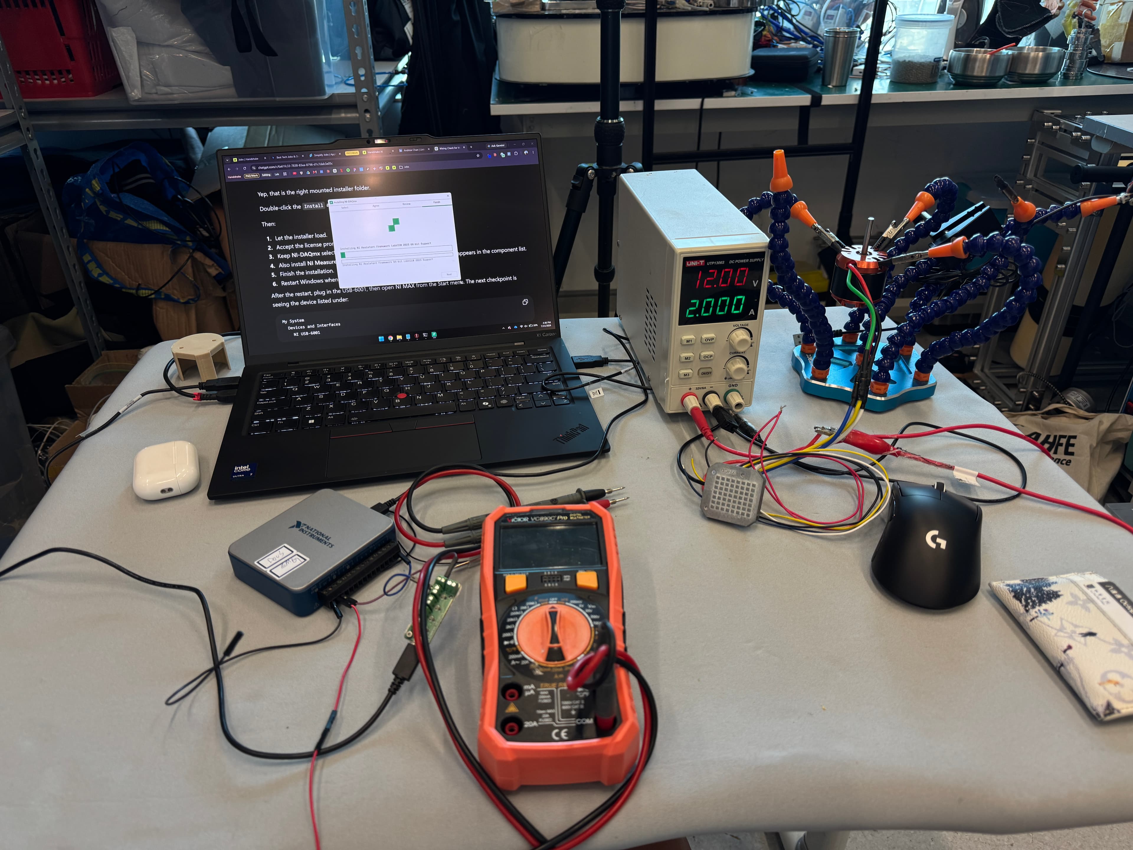
| Bench supply | UNI-T UTP1306S, 0 to 32 V, 0 to 6 A, operating at 24 V |
| Pump | [model, displacement] |
| Relief valve | [model, cracking pressure] — mechanical, set below bladder proof pressure |
Table 8. Power unit hardware.
A unidirectional pump run in reverse does not deliver equal flow, because port sizing, seal orientation and bearing loading are all asymmetric. Contraction and release strokes therefore take different times, which breaks the timing symmetry that reciprocal gait assistance assumes. Fix it by measuring the forward and reverse flow rates and compensating in software, or structurally by fitting a genuinely bidirectional pump. TOPSFLO MG317 was identified as the strongest lead for the structural fix.
Bring up order, do not skip ahead: wire the controller at 24 V with the current limit near 1 A, confirm pole pairs and Hall sequence in OID U-FOC, jog unloaded in both directions, connect and prime the pump with the outlet open to reservoir, then connect the muscle and raise the current limit gradually. Only then move to the Python scripts.
7.1 Rationale for the motor
The original actuator was a Nanjing Ouruike G312XP brushed DC gear motor. It was replaced by a brushless system, currently an XH 4250BL 300KV motor from Guangdong Xinhui Transmission Technology with its paired XHCD controller, driven through an OIDelec OID-RS485-200W FOC controller. Four factors drove the change.
Speed regulation under varying load. A brushed motor run open loop slows as load rises. Pump load rises continuously as the muscle pressurizes, so commanded duty and delivered flow drift apart exactly during the stroke that matters. Field oriented control with Hall feedback holds commanded speed as backpressure builds, which makes pump displacement a usable proxy for muscle contraction.
Reversing duty. The reciprocal architecture reverses direction twice per gait cycle. Brush and commutator wear accelerates under repeated reversal, and gearbox backlash has to be taken up on every reversal before flow resumes. That lost time adds directly to the forward and reverse timing asymmetry described below, on top of the pump asymmetry.
8. Intent Detection
The device must know when to pull. Pull too early and it fights the stance limb. Pull too late and it does nothing useful. The current approach detects the onset of knee lift optically, from a fixed camera viewing the sagittal plane. The IMU path remains implemented and is retained as the deployment sensor and as an independent check.
8.1 Rationale for the camera
The IMU requires the channel index, the sign convention and the mounting orientation to be established before its output means anything, and any change in strap position between sessions changes the sensor frame. A camera measures limb geometry directly in world coordinates. Thigh angle read from hip and knee positions is the same quantity every session, regardless of how the suit was donned. The camera also produces its own visual record, so every detected event can be scored against video offline without a separate ground truth sensor.
Two qualifications on the calibration argument. First, the camera moves the setup work rather than removing it: camera position and height, sagittal alignment, marker or landmark selection, lighting, and the pixel to angle scaling all have to be repeatable. Second, IMU calibration here is a one time code fix, confirming a channel index and a sign, not a per session procedure. The stronger arguments for the camera are the visual ground truth and the immunity to strap shift, not the absence of calibration.
| Property | Camera | IMU | Consequence |
|---|---|---|---|
| Per session setup | Camera pose, framing, lighting | None once the channel and sign are fixed | Camera setup is repeatable but must be documented |
| Sensitivity to donning | None. Measures the limb, not the strap | Strap shift rotates the sensor frame | Main advantage of the camera |
| Drift | None | Gyro bias drift over a session | Camera output is stable over long trials |
| Sample interval | 17 to 33 ms at 30 to 60 fps | 5 ms at 200 Hz | Camera quantizes event timing more coarsely |
| Processing delay | Pose inference per frame, tens of ms | Parse only, negligible | Dominant latency term, see 8.4 |
| Failure modes | Occlusion, lighting change, subject leaves frame | Radio dropout | Camera needs a no detection watchdog |
| Works outside the lab | No, unless body mounted | Yes | Blocks the stairs and community ambulation goals |
| Ground truth for scoring | Built in, video is the record | Needs footswitches or a camera anyway | Camera removes a separate validation rig |
Table 9. Camera versus IMU for intent detection. Neither replaces the other. Camera is the better bench and validation sensor; IMU is the only one of the two that can leave the lab on the patient.
Recommendation: run the camera as the primary trigger for bench and treadmill work, log the IMU on the same clock throughout, and compare event times between the two. That comparison gives the IMU trigger its validation for free, and keeps the deployment path open. If a camera is wanted for deployment, it has to be body mounted, which reintroduces sensor ego motion and a mounting frame, and removes most of the advantage in Table 9.
8.2 Camera setup
Fix the camera on a tripod at knee height, optical axis perpendicular to the plane of progression, 2 to 3 m from the subject, framing hip to floor on the affected side. Lock exposure, gain, white balance and focus, since auto exposure changes the frame interval and destroys timing consistency. Prefer 60 fps at low resolution over 30 fps at high resolution: the event timing depends on frame rate, not pixel count. Record the mounting geometry so the setup is reproducible.
Landmark selection was resolved during implementation, and it did not land on markers. camera_gait_trigger.py runs on MediaPipe Pose directly, through the "solutions" API by default with a fallback to the newer "tasks" API when solutions is unavailable, at a selectable model complexity of lite, full or heavy. Full is the validated default. Landmark smoothing is on by default, which stabilizes the signal at a cost of 60 to 100 ms of added lag; turning it off lowers latency but changes the noise floor, so the onset threshold needs re-tuning if it is disabled. Both legs are tracked every frame, hip, knee and ankle, so leg mode can switch between auto, left and right at runtime with no remounting. The marker pipeline below is retained as a fallback if pose estimation proves unreliable once the exosuit is worn.
8.3 Detection signal
The implemented signal is a height, not an angle, which is a change from the original plan. Camera output is a lift value, hip height minus knee height, normalized by torso length rather than by hip to ankle length, since torso length holds steady while the leg moves. A calibration phase captures the standing baseline first, so standing reads 0.00. Velocity is a least squares slope fit over a rolling window of timestamped samples. Because lift is a height and the IMU gyroscope measures an angular rate, the two sensors no longer output the same quantity; validating one against the other now needs a shape and timing comparison, not a literal overlay.
Detect knee lift onset as lift velocity crossing a threshold in the flexion direction, confirmed over several consecutive samples rather than one, with a refractory period afterward before the next onset can fire. Trigger on velocity rather than on lift height. Height crossing a threshold happens later in the movement, and the latency budget in Table 11 has no room to spare.
| Parameter | Purpose | How it is set |
|---|---|---|
| --leg (leg_mode) | Which leg the trigger tracks | Validated default right. auto compares both legs every frame and follows whichever knee is higher, with swap_margin below to stop it flickering |
| vel_on | Lift velocity that fires stroke onset | Validated bench value 0.49. --auto-vel-on can derive it from the measured standing noise floor instead, capped to 0.40 to 1.50 |
| apex_vel | Velocity at which a stroke ends | Validated bench value 0.15 |
| onset_frames | Consecutive frames above vel_on required before onset fires | Debounce against one noisy sample. Default 2 |
| min_on_time_s | Minimum stroke duration before apex can end it | Default 0.08 s |
| refractory_s | Cooldown after a stroke before onset can fire again | Default 0.35 s |
| max_stroke_s | Hard ceiling on one pump on burst | Default 0.45 s. This is the real stroke size limit, since the DAQ line only has on and off, not a duty value |
| no_detect_timeout_s | Stops the pump when the tracked leg loses trusted tracking | Default 0.30 s |
| watchdog_timeout_s | Stops the pump if the main loop stalls | Default 0.25 s, enforced on a background thread independent of the main loop |
| vel_window | Samples in the velocity fit | Default 5. Costs about half its span in lag, so 5 samples at 60 fps is roughly 40 ms |
| swap_margin | Hysteresis on the active leg in auto mode | Default 0.06 torso lengths. Stops the active leg flipping on a small reading difference |
| max_jump | Continuity gate in single leg mode | Default 0.35 units per frame. Rejects a frame that jumps further than this from the last trusted sample |
| calib_settle_s / calib_hold_s | Time to get into position, then time standing still for the baseline and noise floor | Defaults 5 s and 3 s. Pump held off for both |
| scale_alpha_fast / scale_alpha_slow | Smoothing rate on the torso length reference | Fast during calibration, slow during a run, so one bad frame cannot swing the scale |
Table 10. Camera trigger parameters.
8.4 Latency budget
This is the constraint that decides whether the camera works as a trigger. FR-4 allows 150 ms from gait event to 90 percent of assistive force. The optical path spends part of that budget before the pump has even been commanded. Two contributions are now fixed by code rather than estimated: the velocity fit adds about half of its window's span, roughly 40 ms at the default of 5 samples and 60 fps, and landmark smoothing, on by default, adds a further 60 to 100 ms. Both are switches in the script, not fixed properties of the camera.
| Contribution | Typical range | How to reduce it |
|---|---|---|
| Frame interval quantization | 17 to 33 ms | Run 60 fps or higher |
| Capture and transfer | 10 to 50 ms | Global shutter camera, MJPG, low resolution, drop stale frames |
| Landmark extraction | 10 to 30 ms, pose model only now that markers are not the primary path | Lower model_complexity, or fall back to markers if pose proves unreliable |
| Filtering and differentiation | ~40 ms at vel_window = 5, 60 fps; +60 to 100 ms if landmark smoothing is on | Lower vel_window, or disable landmark smoothing and re-tune vel_on |
| Serial command to controller | A few ms | Already small |
| Hydraulic lag, pump to force | [ ] ms, unmeasured | Section 5.5. The dominant unknown |
Table 11. Latency budget. Measure the optical path end to end rather than summing estimates: flash an LED in frame, trigger the pump on detection, and log both on one clock.
If the optical path alone consumes more than about 60 ms, the camera cannot be the deployment trigger regardless of its other advantages, because the hydraulic lag has to fit in the remainder. Measure before committing.
| Measured total latency | Approach | Work required |
|---|---|---|
| < 100 ms | Reactive threshold detection, current approach | Tune Table 10, proceed to walking trials |
| 100 to 150 ms | Reactive detection with lead compensation | Set LAG_COMPENSATION_S, verify timing against joint kinematics |
| > 150 ms | Predictive gait phase estimation | Adaptive oscillators plus regression, or EMG for anticipatory onset |
Table 12. Sensing strategy gated on measured total latency, from Table 11. This is why the latency and step response tests come before any control architecture commitment.
Do not claim a trained classifier or a detection accuracy figure in any report, poster or CV until walking data has been collected and scored against video. Describe the current method as threshold based optical detection.
8.5 IMU path, retained
Two WitMotion WT9011DCL-RF units stream at 200 Hz and 460800 baud over separate USB radio dongles, so each appears as its own COM port and no demultiplexing is needed. Driver is CH341SER.EXE v3.9. Frames start with header 0x55, flag 0x61, then nine signed 16 bit values parsed with the struct format "<9h" as acceleration, angular rate and angle. The thigh unit on COM5 feeds leg_gait_trigger.py; the shank unit logs knee angle. GYRO_PITCH_INDEX and the sign convention are still unconfirmed. Confirming them costs one printout and gives the camera an independent cross check, so do it even though the camera is now primary.
9. Control Software
All current code is Python on a laptop, using minimalmodbus, pyserial, keyboard, OpenCV and matplotlib. Deployment code will be C on an STM32 Nucleo F411RE or F446RE, for hardware timer determinism, DMA driven UART receive, a hardware watchdog and no laptop tether. Migrate once the trigger logic is validated and assistance timing is stable, not before, or you will debug embedded problems while the algorithm is still changing.
- •pump_control.py. Operational. Direction selected at startup, spacebar toggles run and stop. A heartbeat thread writes register 6000 behind a serial lock; if the heartbeat stops the controller stops the motor. Do not disable this.
- •leg_gait_trigger.py. IMU triggering. Written, not yet validated. Parses the thigh IMU on COM5, runs zero crossing detection, writes duty to the controller on COM6.
- •camera_gait_trigger.py. Optical triggering. Written and running, v2. Bench-validated defaults: leg right, vel_on 0.49, apex_vel 0.15, max_stroke_s 0.45 s. Commands the pump through a single NI DAQ digital run/stop line, not the Modbus duty registers below; see 9.1.
- •arm_imu_tracker.py. Dual IMU 3D visualisation. Run whenever an IMU is remounted, to verify orientation before trusting the data.
Known issue: large duty steps cause pump stutter, because the controller is commanded to jump faster than motor and fluid inertia allow. The fix is to write 1 to register 6001 for speed control mode and apply acceleration ramping instead of duty steps. Registers in use: 6000 heartbeat, 6001 control mode, 6002 current setpoint, 6005 duty setpoint with sign selecting direction.
9.1 camera_gait_trigger.py, as built
Written and running as camera_gait_trigger.py v2. Two things changed from the original specification: pose estimation replaced colored markers, and the motor runs off a single NI DAQ digital line instead of the Modbus registers leg_gait_trigger.py uses. Both are called out below, item by item against what was specified.
- 1.Capture. Matches the specification. Opens the camera, forces MJPG, fixed resolution and frame rate, locks exposure, gain, white balance and focus. Capture runs in its own thread holding only the newest frame, so the detector never processes a stale one. Every frame is timestamped at grab time on a monotonic clock.
- 2.Landmark extraction. Built on MediaPipe Pose in place of the HSV marker pipeline. Both legs are tracked every frame, hip, knee and ankle on each side, plus the shoulders for a torso length reference. Auto mode follows whichever knee lifts higher, with a hysteresis margin so it does not flip on a small reading difference. Pose estimation needs no marker prep or lighting tuning, at the cost of tens of milliseconds per frame instead of a few.
- 3.Signal. Built as a lift value, hip height minus knee height, normalized by torso length rather than hip to ankle length, and referenced to a standing baseline captured during calibration so standing reads 0.00. Differentiated over the timestamped samples, not over frame index, since frame intervals are not perfectly uniform.
- 4.Filtering. The velocity fit is the filter: a least squares slope over vel_window timestamped samples, default 5. Window length is a named, logged parameter, and it trades noise against delay directly, about half its span in added lag.
- 5.Event detection. Built as its own three state machine, idle, rising, hold, rather than imported from leg_gait_trigger.py. Onset fires after several consecutive samples above vel_on. A stroke ends at apex, velocity at or below apex_vel once a minimum on time has elapsed, or at max_stroke_s, whichever comes first. A refractory period follows before the next onset can fire.
- 6.Command output. This is the largest deviation from the specification. The pump runs off a single NI DAQ digital line, run or stop only, no reverse and no duty value. Stroke size is set entirely by how long the line stays asserted, capped by max_stroke_s. leg_gait_trigger.py instead writes SWING_DUTY and STANCE_DUTY to Modbus registers on a reversing pump. Reconcile the two motor interfaces before running both trigger scripts against the same pump.
- 7.Safety watchdog. Built as two independent guards rather than one. A stall watchdog stops the pump if the main loop stops calling pet() within watchdog_timeout_s. A stroke overrun watchdog stops the pump if a burst runs past 1.5 times max_stroke_s, in case the DAQ line failed to release. The pump also stops on lost tracking, on a leg swap mid stroke, on pause, on recalibration, and on emergency stop, which latches until reset. Also stops on keypress and on any unhandled exception, in a finally block.
- 8.Logging. Matches the specification. One CSV row per frame: timestamp, phase, active leg, lift, left and right heights, velocity, state, pump state, event, tracked flag, fault. The on screen overlay draws the skeleton, meters and event trace live; writing it out to an annotated video file is not yet built.
- 9.Modes. Dry run is the default and matches the specification; --live must be passed explicitly to command the pump. --selftest toggles the DAQ line a few times with no camera, to confirm wiring polarity before trusting anything else, which the original specification did not call for but bring-up needed. The LED or screen flash latency test mode in the specification is not built yet, so the optical path latency in Table 11 stays unmeasured. A replay mode does run the full pipeline over a recorded video, so thresholds can be tuned without a subject present, matching that part of the specification.
- 10.Configuration. All thresholds live in one Config dataclass, overridable from the command line, and a run prints its full configuration at startup. HSV bounds no longer apply. Writing the configuration to disk alongside each log file, so every trial is reproducible from its own record, is not yet built.
Build and test it in this order: replay mode on recorded video first, then dry run live with the pump disconnected, then --selftest to confirm DAQ polarity, then live with a short max_stroke_s. Do not connect the muscle until the event timing looks correct in dry run.
10. Status and Next Actions
| Subsystem | Status | Blocking issue |
|---|---|---|
| Artificial muscle | Built | No force or pressure data yet |
| Waist belt | V2 in use | Iliac crest plate not printed |
| Distal cuff | In use | Anchor position to be confirmed |
| Pump and motor | Operational | Stutter at high duty steps; reverse flow asymmetry unquantified |
| Camera detection | Written, v2. Bench defaults validated | Motor interface (NI DAQ run/stop) not reconciled with the Modbus interface the IMU path uses; optical latency unmeasured; not yet run with the muscle connected |
| IMU sensing | Streaming | Channel index and sign not confirmed |
| Trigger software | IMU version written | Neither version validated on live walking data |
| Integrated system | Not tested | Depends on all of the above |
Table 13. Status snapshot.
| # | Action | Output | Depends on |
|---|---|---|---|
| 1 | Confirm physical camera model and mounting geometry against the settings already locked in code (MJPG, 640×480, 60 fps), record walking-in-place footage | Test footage for offline tuning | — |
| 2 | Tune vel_on and apex_vel on that footage beyond the bench defaults (0.49 / 0.15) | Confirmed vel_on / apex_vel for the actual subject | 1 |
| 3 | Build the LED/flash latency test mode, then measure optical path latency | Detection latency in ms | 2 |
| 4 | Bench test muscle with pressure gauge and load cell | Force versus pressure curve | Test rig |
| 5 | Step response test on the muscle | Hydraulic lag in ms | 4 |
| 6 | Sum 3 and 5 against Table 12, confirm the sensing approach | Architecture decision, recorded | 3, 5 |
| 7 | Switch pump to speed control mode with ramping | Stutter resolved | — |
| 8 | Confirm GYRO_PITCH_INDEX and sign, log IMU alongside camera | IMU cross check of camera events | — |
| 9 | Closed loop walking trial, treadmill, low duty | Detection accuracy scored against video | 2, 3, 6, 7 |
| 10 | Print and fit the iliac crest plate | V3 belt | CAD complete |
Table 14. Ordered next actions. Items 3 and 5 together decide the control architecture and should not be deferred.
11. Open Items and Safety
Close these before the document is released or any figure from it is cited: define the target clinical population; agree the FR targets in Table 1; specify anchor geometry and moment arms; verify all citations and complete R8 and R9; state the working fluid and why; confirm the criteria weights with the supervisor and record the date; record the full injection molding parameter set, tool drawing and storage location; document the winding machine and its settings; record end fitting and crimp design with a cross section; photograph all belt versions; confirm whether the anchor is above or below the knee; insert the hydraulic schematic; record pump model and measured flow asymmetry; confirm the physical camera model and mounting geometry, since frame rate and capture settings are already locked in code; build the LED/flash latency test mode and measure the optical path latency to fill Table 11; reconcile the camera trigger's NI DAQ run/stop motor interface with the Modbus duty interface the IMU path uses, before running both against one pump; confirm GYRO_PITCH_INDEX and sign; record IMU scale factors; confirm whether speed control mode was implemented; complete the bill of materials; confirm ethics approval status for any human subject work.
Safety controls, all mandatory. A mechanical relief valve set below bladder proof pressure, not a software limit. A mechanical fuse at the anchor sized to a known failure force. The controller heartbeat watchdog never disabled. The no detection watchdog on the camera trigger, which stops the pump when landmarks are lost. Interface pressure under 20 kPa with skin inspection before and after every session. Leak testing of every muscle at operating pressure before it goes near a person. An overhead harness or parallel bars and a second person with a kill switch for every walking trial. Never raise duty in large steps, never bypass the relief valve, and always verify the trigger in dry run before connecting the muscle.